6.Sync Box Settings
Introduction to the Sync Unit
The Sync Unit is used to achieve synchronization between NOKOV optical motion capture cameras and external devices. Its sync input supports both professional video Genlock synchronization signals and standard TTL-level sync signals. The sync output function can output multiple TTL sync signals to trigger and synchronize multiple external devices.
A physical view of the Sync Unit is shown in Figure 1.
.png)
The sync input interface on the front panel of the Sync Unit is shown in Figure 2.
.png)
On the front panel, the Sync Unit includes 5 groups of BNC interfaces. The main functions and features of these interfaces are as follows:
A: 5V General TTL Sync Output Interface This includes four BNC connectors, each capable of independently outputting TTL sync signals (digital signals at 5V level) for triggering and synchronizing multiple external devices. These sync output interfaces must be used in conjunction with a sync input interface.
B: 3.3V General TTL Sync Output Interface This also includes four BNC connectors, each capable of independently outputting TTL sync signals (digital signals at 3.3V level) for triggering and synchronizing multiple external devices. These sync output interfaces must be used with a sync input interface.
C: General TTL Sync Input Interface A BNC interface that supports TTL digital signals, with two inputs at 5V level and two at 3.3V level. It is used to receive TTL sync trigger signals from other devices.
D: Genlock Sync Input Interface A BNC interface with 75Ω impedance, supporting SD (Standard Definition) Black Burst or HD (High Definition) Tri-Level analog signals. It is used to synchronize and lock NOKOV optical motion capture cameras to an external video source.
E: Remote Start Input Interface Used for remote control to start playback; feature under development.
F: Trigger Sync Input/Output Interface A BNC interface with TTL digital signals at 5V level. External devices can use this interface to trigger and synchronize NOKOV optical motion capture cameras.
G: Isolated Sync Input Interface Used when the sync source voltage is higher than the standard logic level of 5.0V or when different reference levels are involved.
H: Remote Stop Input Interface Used for remote control to stop or pause playback; feature under development.
I: ExtIO Input Interface ExtIO expansion port; feature under development.
J: VESA In / VESA Out Interface VESA video sync input/output interface; feature under development.
K: POE Connection Port When the Sync Unit needs to synchronize with the camera, connect one end of the Ethernet cable to the POE port of the Sync Unit and the other end to the switch connected to the 201 camera.
L: 12V Power Interface and Power Indicator Light The indicator light turns on when POE is connected or a 12V power source is plugged in.
Note:The Sync Unit cannot respond to multiple sync input signals simultaneously. Only one sync input interface should be used at a time.
Operating Instructions for the Sync Unit
The usage of the Sync Unit is as follows:
(1) When using the Genlock synchronization function, connect the Genlock output signal from an external sync source (such as a Genlock signal generator or professional camera) to the Genlock In interface of the Sync Unit using a BNC cable. At the same time, ensure that both the Sync Unit and the NOKOV optical motion capture cameras are connected to the same network. The Sync Unit will synchronize with the NOKOV cameras through the network.
.png)
.png)
.png)
(2) When using the Trigger sync function, connect the 5V TTL trigger signal from an external device to the Sync Unit’s 5.0V TTL In interface using a BNC cable. Then connect both the Sync Unit and the NOKOV optical motion capture cameras to the same network to achieve synchronization via the network.
(3) Usage of General TTL Sync Input and General TTL Sync Output Interfaces Using the general TTL sync input and output interfaces, the NOKOV optical motion capture cameras can trigger and synchronize multiple external devices. Likewise, external devices can simultaneously trigger and synchronize the NOKOV cameras and multiple other external devices.
· When the NOKOV cameras need to trigger and synchronize multiple external devices, connect the sync output cable of the NOKOV cameras (white RCA plug) to the Sync Unit’s general TTL sync input interface C using a BNC-to-RCA adapter cable. Then, connect the general TTL sync output interfaces A/B to the external devices that require triggering and synchronization using BNC cables. The general TTL sync output interfaces can connect to and trigger up to 8 external devices simultaneously.
· When external devices need to trigger and synchronize both the NOKOV cameras and other external devices simultaneously, connect the trigger output signal of the external device to the Sync Unit’s general TTL sync input interface C using a BNC cable. Connect the sync input cable of the NOKOV cameras (red RCA plug) to one of the BNC interfaces in the Sync Unit’s general TTL sync output interfaces A/B via a BNC-to-RCA adapter cable. Then connect the remaining BNC interfaces in A/B to other external devices that require triggering and synchronization. In this setup, external devices can simultaneously trigger and synchronize the NOKOV cameras and up to 7 additional external devices via the general TTL sync input and output interfaces.
(4) Connect the POE switch to the Sync Unit via network cable to supply power to the Sync Unit. Alternatively, use the DC 12V power adapter provided with the Sync Unit to power it.
(5) At this point, the Sync Unit can realize the trigger and synchronization functions between the NOKOV optical motion capture cameras and external devices as needed.
Operation of the Sync Unit with Software
Taking the Bertec force plate and time code as an example:
(1) First, connect the force plate device to the Sync Unit. Then connect one end of the network cable to the switch and the other end to the POE port on the Sync Unit.
.png)
Connection Between Force Plate Device and Sync Unit
(2) Open the software and connect the cameras. After connecting, the software will display the number of cameras and Sync Unit devices. Click Settings and select Sync Unit Settings. In the Information section, choose the Sync Unit device, then check the option for Internal Clock Input Source Setting. Select Input Mode 2 and set the output to TTL Out 1 Output Mode 1 (the first option in the drop-down list). Click Play and configure the force plate to apply force.
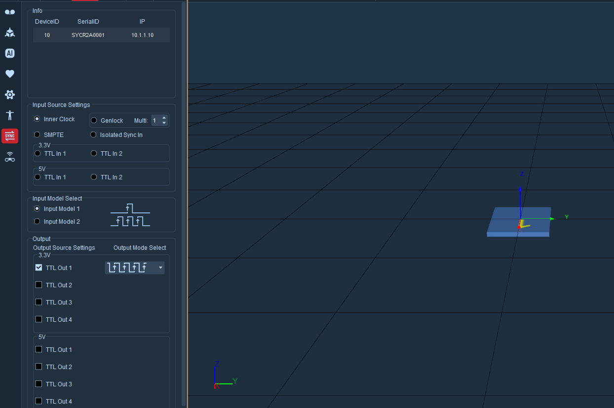
Force Plate Configuration and Sync Unit Configuration
Using the time code as an example:
(1) First, connect the time code to the Sync Unit using a sync cable. Press and hold the power button on the time code to turn it on.
.png)
Connection Between Time Code and Sync Unit
(2) Open the software and connect the cameras. Click Settings and select Sync Unit Settings. In the Information section, choose the Sync Unit device, then check SMPTE, select Input Mode 2, and set the output to SMPTE.
(3) Click Data Broadcast, scroll down to Time Code, and turn on the enable switch. Set the port to 5850 and the SMPTE Format to 24fps (matching the time code device). After clicking Play, the time displayed in the lower-left corner of the view will match the time code.
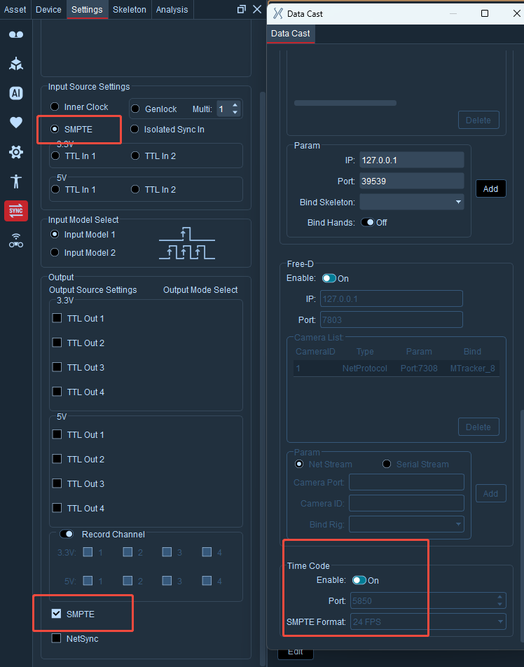
Time Code Configuration
Sync Unit Software Features Overview
Input Source Settings
Internal Clock: Built-in sync trigger switch
Genlock-Multiplier: Synchronous frequency multiplication trigger input;
SMPTE: Time code setup switch
Isolated Sync In: Isolated sync input interface
3.3V / 5V: General TTL sync input interface
Input Modes
Input Mode 1: PWM rising edge triggers once
Input Mode 2: PWM rising edge triggers continuously
Output Source Settings
3.3V / 5V Output Mode: General TTL sync output interface with 4 BNC connectors. These can output the same TTL sync signal simultaneously or be individually controlled to output different signal modes, used to trigger and synchronize multiple external devices. The sync output interface must be paired with the sync input interface of other devices.
Recording Channels: When a channel is checked, it outputs the recording sync signal. In idle state, the channel outputs low level. After clicking the start recording button, the channel outputs high level and holds it. After clicking stop recording, it outputs low level and holds it.
SMPTE: The sync input interface implements triggering and synchronization of NOKOV optical motion capture cameras.
NetSync: NetSync is a network synchronization feature used to synchronize with external devices via network. The data format is publicly available.