(1)Rigid
- The XINGYING software supports the creation of Markersets in Live. This requires objects with pre-attached reflective markers to be placed on the site, and each reflective marker point must be visible in the 3D view of the software ( 9.1.1).
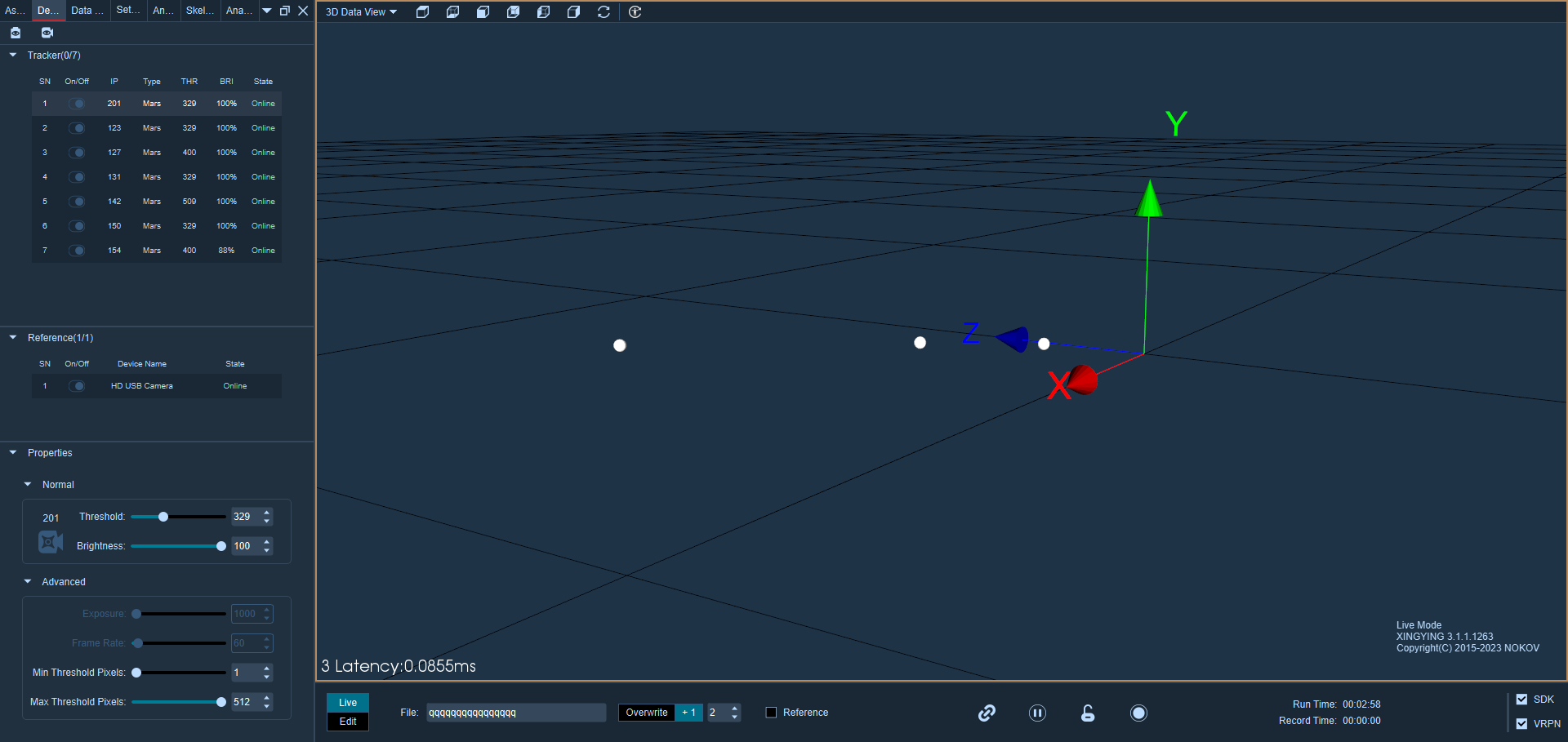
9.1.1
- Confirm that the software is running, then click the "Freeze" button at the bottom of the interface to freeze the 3D view.
- To select reflective marker points in the 3D view, hold down the Shift key, click and hold the left mouse button, and drag to box-select the points needed to create a rigid body. Alternatively, hold down the Ctrl or Shift key and use the left mouse button to select the reflective marker points for the rigid body one by one. Use the mouse to select multiple reflective marker points attached to the surface of the rigid body in the 3D view. Note that a rigid body must have at least 3 reflective marker points (9.1.2). After selecting unnamed points in the freeze frame, the number of unnamed points will be displayed in the lower left corner of the 3D view in Live. The numbers in parentheses represent the number of boxed points, while the numbers to the left represent the total number of marker points in the 3D view. \
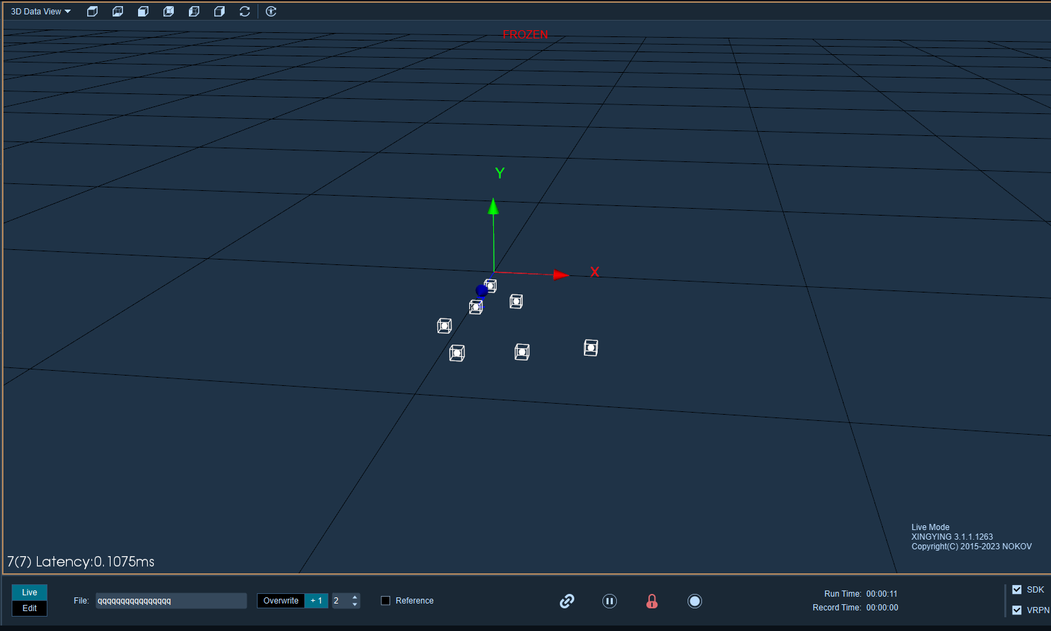
9.1.2
Create a single rigid body.
- In the 3D view, select the highlighted points that need rigid bodies and freeze frames (the number of marker points required for creating rigid bodies ranges from 3 to 19). Right-click with your mouse and choose "Create Rigid Body." In the rigid body creation window, you can customize the name of the created rigid body. (9.1.3)After customizing the name of the rigid body, choose to create either a "single" or "multiple" rigid body.
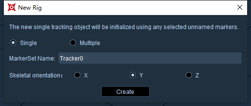
9.1.3
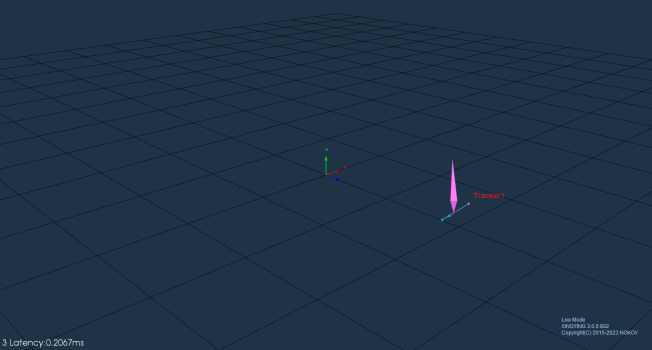
- Choose "single, " then click on "Create." Multiple points will form a Markerset, and the reflective markers will be named and connected. The software defaults to creating rigid bodies in the positive Y-axis direction.
9.1.4
Creating Multiple Rigid Bodies
- The function of creating multiple rigid bodies is mainly used for scenes with a large number of rigid bodies, such as drone swarms. It allows for the quick creation of multiple rigid bodies. Before using this function, it is important to evenly distribute the objects in the scene. The distance between the objects should be kept as consistent as possible, and the spacing between the reflective markers on each object should also be consistent. The distance between the objects should be as consistent as possible, and the spacing between the reflective markers on each object should also be uniform.
.png)
9.1.5
- Selecting reflective markers is not necessary. In the rigid body creation window, choose "multiple, " set the bone direction and field radius, and then click "create." Multiple rigid bodies will be successfully created.
- The maximum number of rigid bodies that can be created is 100. When the 101st rigid body is created, the software will display a prompt.
- Click the "Freeze" button to unfreeze the 3D view. At this point, the active captured object will be visible, and the MarkerSet will follow the activity of the captured object in real time. In this state, data can also be directly collected.
Note
The software does not allow rigid bodies to have the same name. If there is a duplicate name during rigid body creation, the "create" button will be grayed out and cannot be clicked. Please change the rigid body's name to proceed, or alternatively, delete the duplicate .mars files in the current working directory before creating a new one.
If there are non-sequentially numbered rigid body names in the working directory, the software will prioritize generating rigid body names with lower numbers by default when creating new ones.
Without modifying the names of the rigid bodies, creating a single rigid body will default to incrementing from " Tracker0, Tracker1..." onwards. When creating multiple rigid bodies, the names will default to incrementing from " MTracker0, MTracker1..." onwards.
The orientation of the rigid body is determined by two points.
- You can customize the orientation of a rigid body during its creation. The specific operation method is as follows: after freezing, press the Ctrl key and select the Marker points in the 3D view with the left mouse button. After successful creation, the orientation of the rigid body will be directed from Marker1 to Marker2. This determines the orientation based on the first and second Marker points selected with the Ctrl key.
Change the 6DoF of the rigid body
- After creating a rigid body, its skeleton can be displaced and rotated.
- Click the freeze button, select the skeleton name of the rigid body in the asset panel, and then click on the X/Y/Z axis offset below. A cross (9.1.5) will appear in the center of the rigid body skeleton in the 3D view. Dragging an axis of the cross will displace the skeleton, or you can click on the center point of the cross to drag the skeleton along any axis.
.png)
9.1.5
- In the frozen frame state, the skeleton can also be rotated. Click on the X/Y/Z rotation axis of the skeleton, and the center of the skeleton will display a rotating three-dimensional ring.
.png)
- To exit editing the displacement and rotation of the skeleton, press Ctrl to leave the editing state. The cross and ring will disappear. After unfreezing, the displacement and rotation of the skeleton will be reflected in the 3D view.
The rigid body skeleton moves to a specified marker point.
- In live or edit mode, the rigid body can be moved to a specified marker point.
- In Live mode: While in freeze frame, select the rigid body's skeleton, click "X Offset" in the asset panel, and then click on a specific marker point in the 3D view. The skeleton will move to the specified marker point.
- In Edit Mode: Right-click to enter Model Pose mode, click "X Offset" in the asset panel, and then click on a specific marker point in the 3D view. The skeleton will move to the specified marker point. Exit Model Pose mode, click solve, and after the solve is complete, the skeleton will move to the specified marker point.