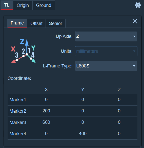
Before calibration, it is necessary to determine the calibration axis. The set calibration axis determines the upward axis (Z or Y) in the global coordinate system after calibration. According to the length of the L-shaped calibration rod you are using, set the type of the L-shaped rod in the software (if you are unsure about the type of the L-shaped rod, you can consult our technical engineers);
Open the calibration panel and click the gear icon on the right. Under the "Calibration Frame" option, confirm the coordinate system definition needed. You can select the coordinate system as Z-axis upward or Y-axis upward by "Calibration Axis". In the "L-shaped Rod Type" dropdown, select the corresponding L-shaped rod size. The size of the L-shaped rod is related to the purchased L-shaped calibration kit. Measure the distance between the two Marker points at the farthest end of the longest side of the L-shaped calibration rod to determine the size type of the L-shaped rod. For example: If you measure the distance between the two Marker points at the farthest end of the L-shaped rod to be 600mm, then the L-shaped rod type you use is "L-600". The last letter of the L-type rod type means: S represents a flexible L-type rod, R represents a rigid L-type rod (default is rigid), and FP represents applications related to the force platform. You can also customize the L-type rod type. In the dropdown box, select "Manual" to manually input the X, Y, and Z coordinates of each Marker ball in the "L-shaped Rod Coordinates" table below;
Coordinate System Switching: After loading the calibration file, you can switch the Z-axis and Y-axis in the calibration frame settings. After switching the axis, the 3D view coordinate system becomes the set axis.
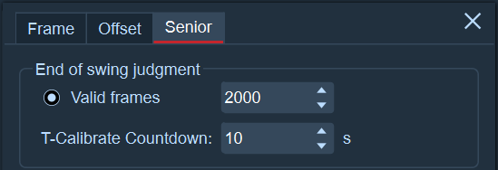
Valid Frames per Camera: During T calibration, each lens must reach the set number of effective frames for the T calibration to be completed. Otherwise, the T calibration progress will remain at 99% and wait for the number of frames collected by the lens to reach the set number. During T calibration, you can view the current actual collected effective frames and the set frames in the upper right corner of the 2D view.
Calibration Countdown: The countdown setting after clicking the T calibration button.